
On the last installment, I left you hanging with the next visit – the machinist.
I took my poorly crank case halves to Jonathan at Stanwood Engineering. I took the recommendation from Duncan at Westwood Liners, as he had his hillclimb Cayman 3.9 competition engine built there. Immediately, I felt like I was in good company, spotting various Porsche engines there amongst other race engines, and his turbo Lotus Elise S1 that he competes with.
Jonathan started by putting the crankcase halves into the oven to remove the cylinder liners and see what had happened. Sure enough, the previous engineer took out too much material from the crank case, which is what allowed it to slip over time. He gave me a couple of options. The first was a wet liner conversion and thread repair to my existing crank cases, to finish the repair of the timing chain tensioner thread. The other was a far less costly and quicker option to buy some spare M97.01 crank cases he had on the shelf and reliner those. We did some non-destructive testing to ensure they did not have any cracks or flaws that would otherwise cause me problems, then agreed to go for the latter option. Of course, a 100mm overbore was thrown in as part of the package, so I could fit my forged pistons from Mahle to take the engine to a 3.9. A nerdy detail – we both agreed to run a slightly larger clearance than what Mahle specifies; my experience of TVRs is that ductile iron liners need a wider clearance than what Mahle suggested for longevity. Note that this will impact my decision on oil to use later.
Jonathan has fitted the liners; however, he closed up shop for Christmas before he could finish cutting the deck of the crankcase halves. That excitement will have to wait until the next installment.
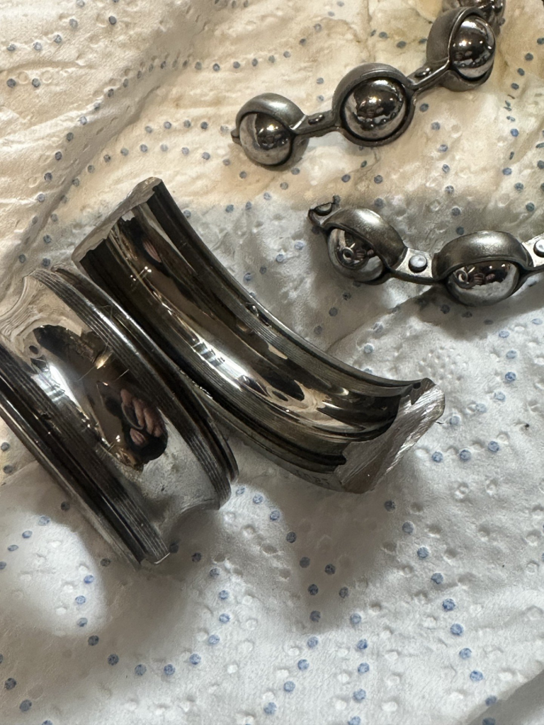
While Jonathan had my crankcase halves, I decided to measure up my crankshaft and carrier to triple-check that it had no flaws that needed remediation. This means disassembly of the crankshaft carrier and inspection of the bearings, before I can do any measuring. I’m glad I tore apart the crank case carrier. I found some paint in an oil gallery, and a scored bearing that, by some miracle, took all of the damage rather than the crankshaft.
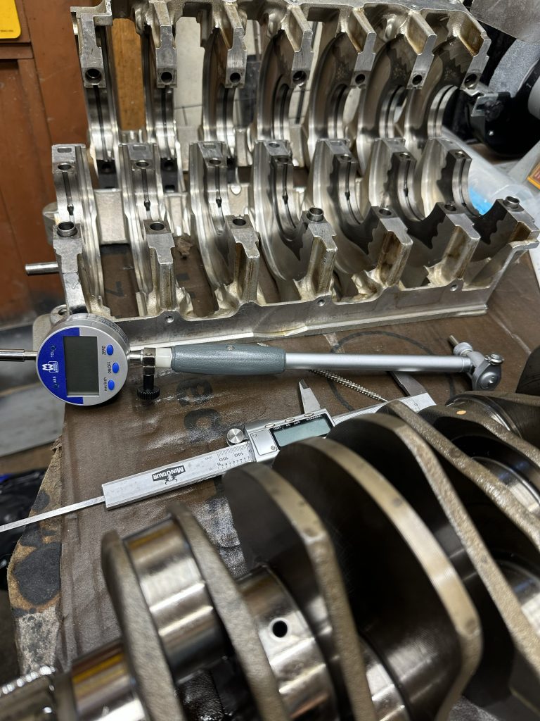
Measuring the bore with a bore gauge and my trusty Moore and Wright digital DTI
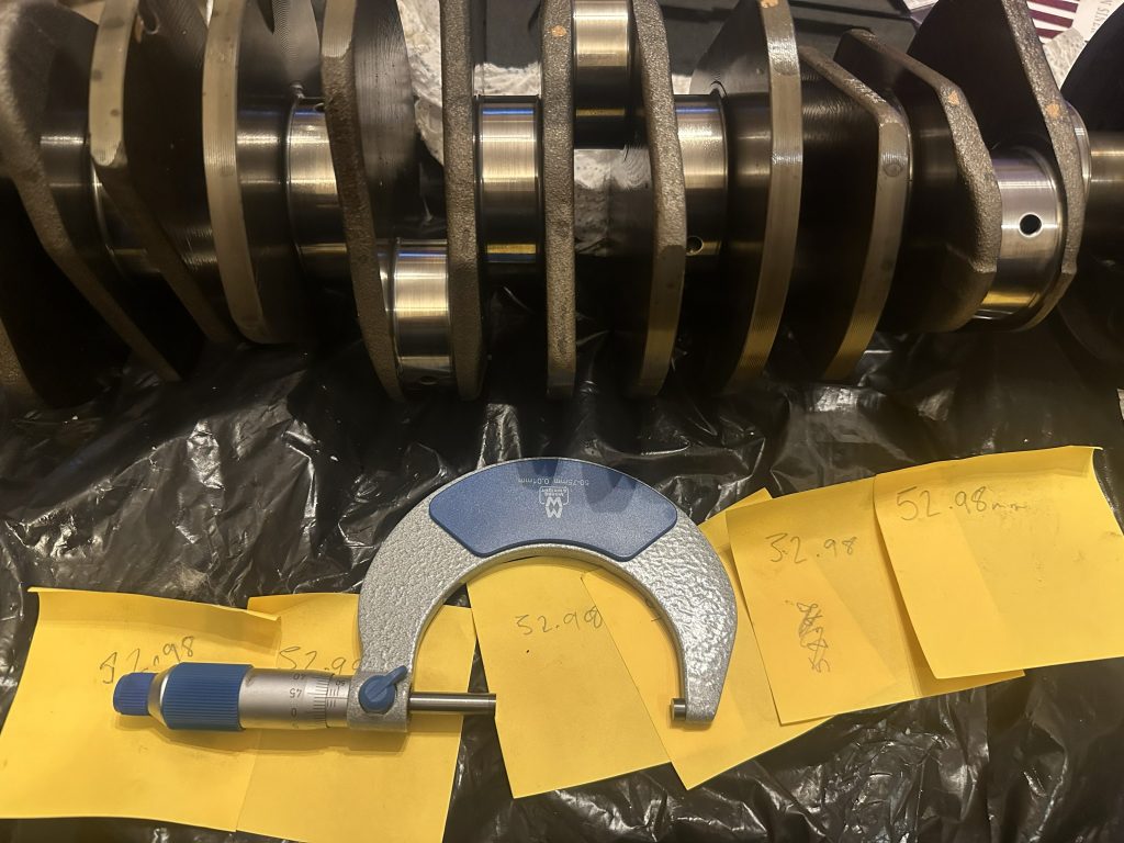
…and my Moore and Wright 50-75mm micrometer.
After an initial visual inspection, some accurate measurements of journal thicknesses and roundness had to be made, as well as measuring the crank to ensure it was straight and true. This involved a trusty calibrated micrometer, a DTI gauge, some patience, a lot of Post-it notes, and notepads. Thankfully, the crank measured within the tolerances posted by Kolbenschmidt (the folks who make engine bearings for Porsche) and the Porsche workshop manual.
At this point, I decided to deep-clean the galleries of the crankshaft and crankshaft carrier. To start the process, I left the components soaking in a 40:1 mix of white spirit and new gear oil (Honda DPSF that I was never going to use – which feels a lot like ATF with different additives). This is great at degreasing and loosening grime, without the risks of water-based degreaser causing flash rusting. Obviously, white spirit is not brilliant to breathe, and it is flammable if you try hard enough, so some sensibility needs to be applied when using it. I like it as it doesn’t leave an overly oily film, which diesel does.
Next, some long brushes for cleaning oil galleries are used to push and scrub any grime out of the ports. This is done with some carburettor cleaner to help loosen anything the white spirit hasn’t managed to free.
After that, 120psi of air ought to move whatever is left in there!
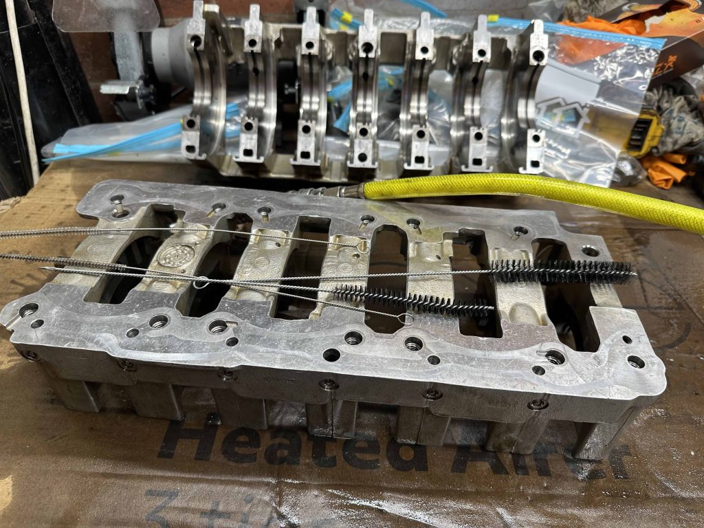
This was a worthwhile process, as I found another flake of paint inside one of the main journal oil galleries.
At this point, I did a side-quest to buy all the bottom-end seals, gaskets, bolts, plugs, and dowels. I may publish a reference on my tuning developments site at a later date, as I managed to cross-reference a lot of OEM Elring components with their Porsche numbers.
I also did some research into sourcing the correct bearing for an OEM replacement – in short, an NSK 6305DDUA17CG25 – as the revised Porsche IMS bearing in later cars is sufficient for the lifetime of the engine in a road car.
The insides of an NSK 6305DDUA17CG25 after approx 135,000 miles – no wear marks. Both seals left in tact.
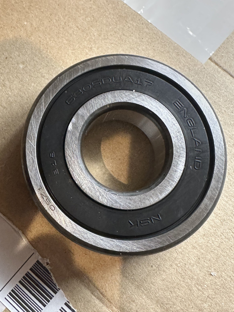
A brand new NSK 6305DDUA17CG25 – OEM IMS Bearing replacement for MY05 onward 911, Boxster, and Cayman.
There’s a lot of controversy around bearing seals and this, that and the other. I have decided it is better to leave them in place in my new engine, as the risk of contamination from metals that often are deposited during a break-in period is greatly reduced. Given that the IMS bearing will sit in oil, and there is still a risk that swarf may not get sucked and pumped into the filter before coming in contact with the IMS bearing, it is a no-brainer to leave the seals in place, especially when pairing the rings I am using with ductile iron liners. Clearly, having both seals in place for the life of the IMS shaft has not caused an issue besides the seals eventually breaking down – so perhaps when I change a clutch, I might follow this trend of removing a seal.
I also did some research into the lubricant Porsche and NSK specify for the revised IMS bearing, again another technical article for my development site. The bottom line is the kinematic viscosity at comparable temperatures is similar to that of 10w60 oil.
Moving on to more interesting things, I mentioned in my last post that I was going to get some headwork done. Namely, I have contracted Ric Wood of CNCHeads/Ric Wood Motorsport to CNC port the heads, hand-finish the ports and chamber, replace the valve guides, skim the heads, do a multi-angle valve job, and clean the heads up. Before I did this, though, I wanted to disassemble my heads so I could properly clean the valvetrain, including the lifters.
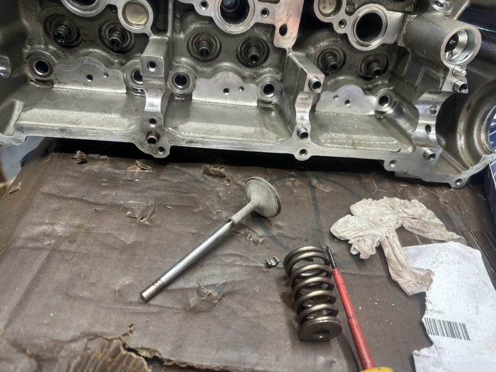
Removing the valves – you can see the exhaust valves have been faced with their fair whack of oil in their life
I organised each lifter, spring, perch, washer, keeper, and collets so I could return them to the original valve when I get the heads and valves back from Ric. I used some heat and needle-nose pliers to gently remove all of the valve stem seals.
I floated the progress with a close friend of mine – Alan Smith – a retired engineer who helped me cut my teeth on engineering! He asked me what I thought about the intake plenum and runners, and if I needed to port those. I observed that the advantage of injection-molded plastic manifolds is that they are incredibly smooth from the factory. However, I did see some flaws that can be ironed out.
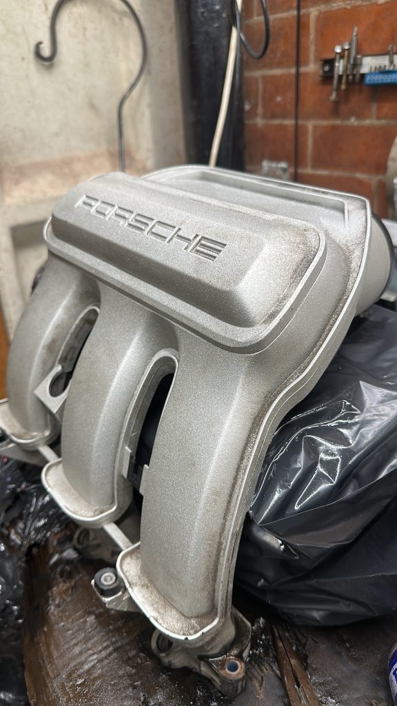
Yes, these are plastic; they are very convincing!
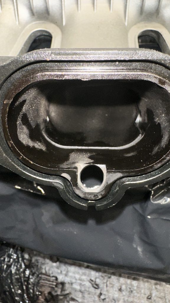
The bottom of the runner has a small lip. I think some surface prep, epoxy and sanding might be in order to remove the edges, otherwise they will induce turbulence and affect the velocity of the other side of the port – which we want to promote.
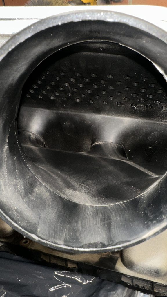
Some small imperfections on the input – again, a big lip – the picture doesn’t show how bad that really is. I am impressed at how neat the internal plastic welds are from where two pieces have been joined during the manufacturing process.
Regarding airboxes, I found that some individuals have shared similar thoughts on dual decklid intakes. 997.2 airboxes seem to have this covered. So it seems I may have an off-the-shelf option to explore before considering further developments here. Or at the very least, I have a good starting point to scan and modify in CAD…
I also had another thought on cams, as I was planning to run the standard cams. I discovered Schrick manufactures some fast road camshafts for the 996 and 997. I cannot find a baseline of duration or lift for the standard cams to determine if any other cams are going to be suitable for this engine. So I have decided that I will assemble the longblock with standard cams when everything is back, get the DTI out, and measure the standard cams. I will probably publish the specs on my development site when I put it back together. It did strike me that if I run the bottom end clearances a bit looser with an oil like 10w60 to compensate, and run some ARP crankshaft carrier bolts, then I could increase the RPM of the motor and take advantage of some extra lift and duration.
To finalise this chapter, I decided to protect the bottom end crank assembly by assembling it loosely, protecting it with oil and assembly lube, then sealing it in a few bags.
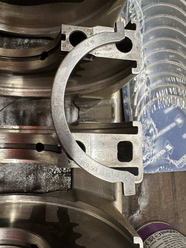
A thrust bearing supplied by Porsche Centre South Lakes – note the KS stamp!
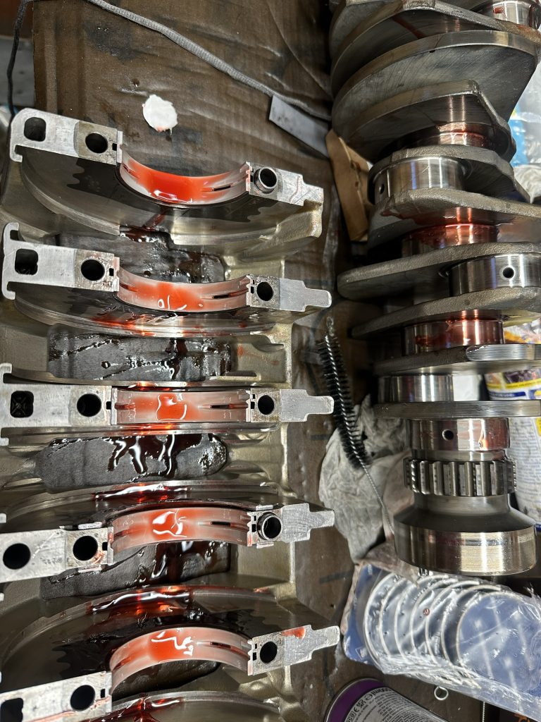
Plenty of strawberry sauce… Or is it Permatex ultra slick assembly lube?
That’s all for this episode. January should bring the actual assembly of the bottom end, and then some heads to measure so I can order the head gaskets from Cometic. Progress is slow but steady, which is good!
Leave a Reply