“Where’s the engine, Ciaran? Is it in the car yet?!” I hear you ask. I suppose I ought to stop driving it about and give you the long-winded answer, as that’s probably what you’re here to read!
It’s in the car. It’s brutal. A couple of tweaks need to be made before I send it to Wayne at Chipwizards to work his magic. With all that said, happy bunny status has been achieved.
In the last episode, I left you with a view of some main journal bearings and some strawberry sauce (Permatex lube). I’ll jump to the next part.
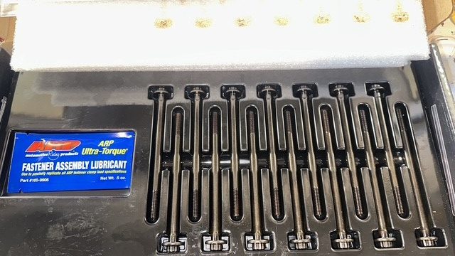
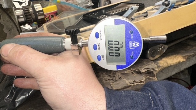
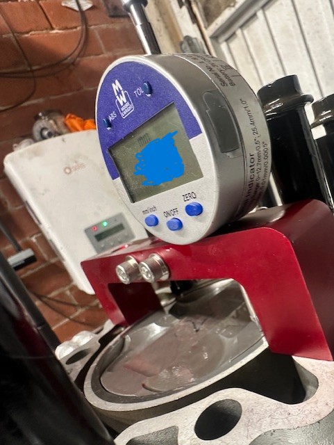
I fitted the ARP main bolts, torqued them down using their ultra assembly lube, and measured the main journals before going any further. The advantage of ARP bolts here is that they are stronger than standard bolts, which offers far less deformation of the bore during heavy loads on the crankshaft, which will come from me making more power. The other is that I can re-use the ARP main bolts as many times as I like, whereas I seem to recall the Porsche bolts only surviving two torque-yielding cycles before having to be binned. To my satisfaction, all the bores measured perfectly round with the ARP mains torqued up, precisely at 64mm to my dial gauge.
After confirming the crank clearances were what I wanted, I installed the crankshaft, torqued it down, and installed the IMS timing assembly.
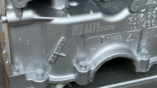
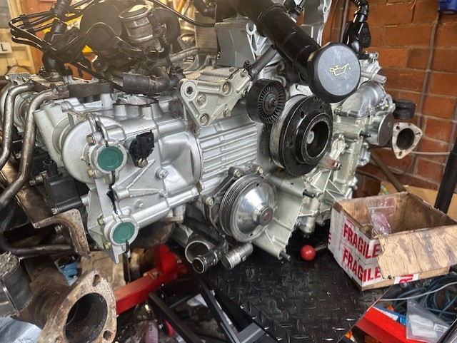
At this point, I picked my crank cases up from Jonathan at Stanwood Engineering. I was thoroughly impressed with the finish of the liners. Even more impressive was how perfect the bores measured up across the two crank cases. So then came the scope creep. I thought if it looks that good on the inside, it’d best look that good on the outside too. Cue the Yellow Zinc-plated fasteners and Aluminium Silver VHT paint. I opted for Paragon’s high-heat, oil-based paint system as flat sixes tend to run very hot. The colour and ease of spraying on an HVLP gun are fantastic. However, I do wish I had explored a 2K VHT lacquer, as I think that would’ve been a bit more durable in hindsight.
Fresh out of the gun. This took hours to mask.
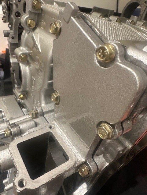
Inspired by the idea of an engine being a “jewellery box”, I went for this silver and gold theme.
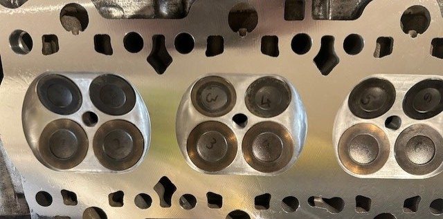
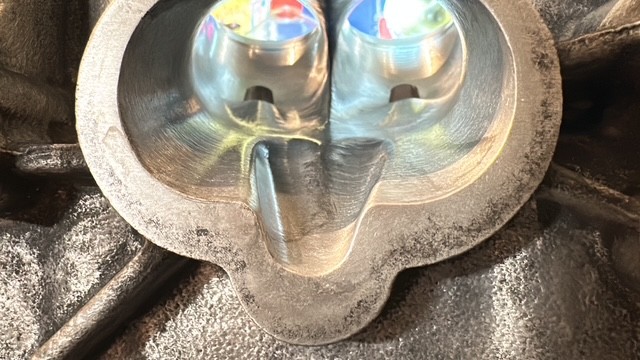
Next came the collection of my heads from Ric Wood. I asked him to profile them for my 3.9 as a “stage 2” and noted that I would be porting the inlets to improve their flow, too. He did not disappoint. CNC-porting the shape of the inlet and exhaust, then hand-finished for the perfect surface texture. Valve guides replaced with stronger Colsibro types. Valve seats are cut with multiple angles, and valves back-cut very slightly to aid both the flow and velocity of the air/fuel mix into the combustion chamber—all super trick stuff you expect to see on performance heads.
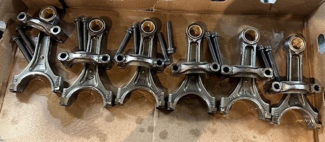
After I spent enough time drooling over my new cylinder heads, I decided to start doing the refurbishment of my connecting rods and balancing of the assembly.
Balancing helps in blueprinting in many ways:
- A fully balanced assembly means less power is lost due to inertial instability
- Pistons and rods exert a more consistent force across the crankshaft, leading to better wear characteristics in high-load scenarios (not seen as much in street-driving, to be fair)
- The reduction in inertial instability across the crankshaft also means that the engine can comfortably rev higher (with supporting mods)
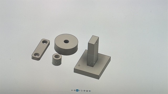
Dynamic balancing – where the counterweights on the crankshaft are balanced to match the weight of the rods and pistons – requires the rods and pistons to be balanced first using a process called static balancing, which became my clear starting point. All of the equipment to do static balancing at home is often expensive and can typically only be found in the United States, where great expense has to be made on both import tariffs and the jig itself. Unless, of course, some ingenuity is employed with some jewellery scales and a 3D printer. So here came my rod balancing jig.
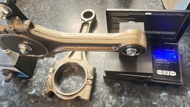
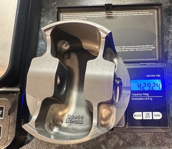
You may ask if you need the scales to be calibrated; the answer is no in this case. The goal is to use the scales as a comparator, so the focus is more around consistently being able to weigh the pistons and rods back to back, after grinding them, to get them within an acceptable weight range. I found my original rods and pistons were up to 5g apart from each other, which I was gobsmacked by. Clearly, the dual mass flywheel compensates for this, but it would explain why some folks with lightened flywheels on standard engines manage to crack their crankshafts.
Most engine builders go for 1g for up to 8,000RPM use on the track. I decided that, with my glutton for punishment, I’d aim for 0.1g. To achieve this, I ended up temporarily gluing the jig together onto some old board, which I attached to the kitchen bench, while my ever-patient significant other was away. This involved lots of walking to-and-from the garage, where some die-grinding would be performed, and then subsequently checked against the lightest piston or rod.
Once I had balanced the rods and pistons, I matched them up to ensure the total weight of the assemblies was within 0.1 g. Then I employed Blackpool Road and Rally to rebush my connecting rods with Porsche OEM bushes to a clearance we both agreed on for the motor. After the work, the necessary triple-checking was performed again, all the balancing was perfect.
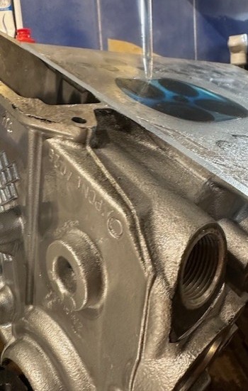
So the “boring bit” of “test assembling” the short block had to happen, so I could make sure all of my critical measurements were correct. This means revisiting the cylinder heads with the engine put together, so I can work out what size head gasket to use and if any further machine work needs doing to the block.
The unfortunate part of deshrouding the valves on a stage 2 head to increase flow is that the combustion chamber volume increases very slightly, which reduces the compression of the engine. However, I have only reduced in real terms from 11.8:1 to 11.5:1 on the finished engine, and gained a bonus in the midst of it. Running a slightly tighter head gasket to compensate has allowed me to get the “quench” size exactly where I want it, which should improve torque over the standard Porsche engine. This works by improving the speed at which the flame can travel across the piston.
Measuring for the right size and compromise during the blueprinting process involves measuring the heads using a burette filled with screenwash and a plexiglass plate, using a “deck bridge” with a DTI gauge to measure the piston-to-deck clearance, and then re-decking the block to get the critical measurements correct. It has taken a few years to put together, but I have an Excel spreadsheet that helps calculate the ideal measurements based on variables about the engine’s characteristics. It is an expensive process in both time and money, but the results are well worth the effort if you are serious about blueprinting.
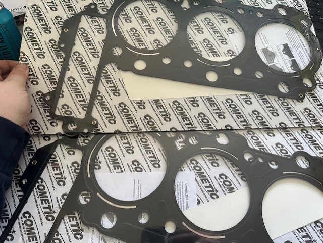
All of that, to work out what fraction of a millimetre difference would make! These details matter when trying to squeeze as much out of a naturally aspirated engine as possible. Once I was happy, I placed a priority order with Summit Racing and waited a week for my Cometic head gaskets to arrive.
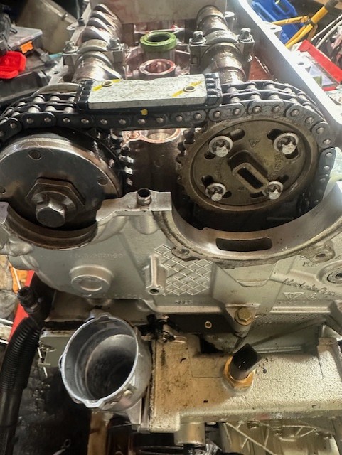
Eventually, final assembly. Crank cases together, rods and pistons reinstalled, I can start installing the head gaskets and cylinder heads, along with all the new timing chains, IMS bearing, the whole nine yards.
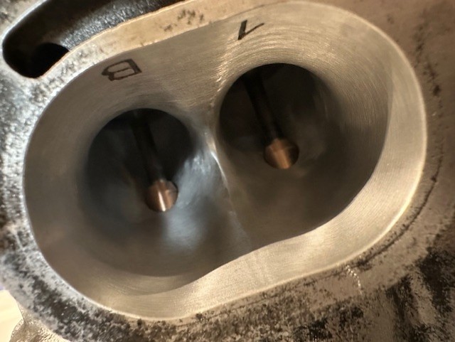
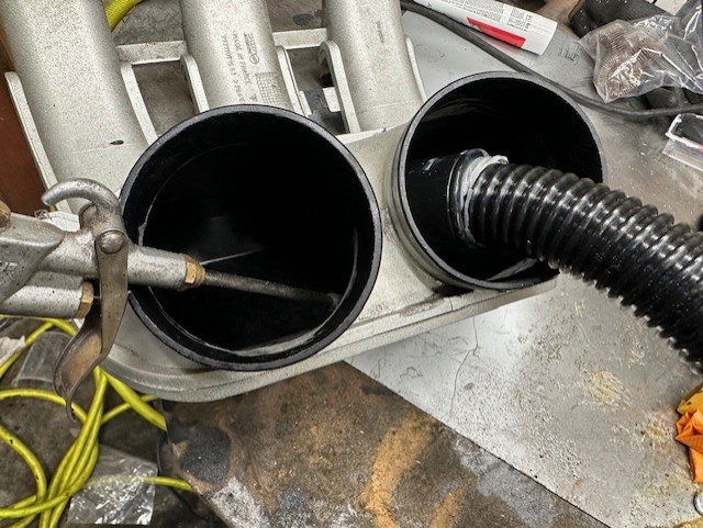
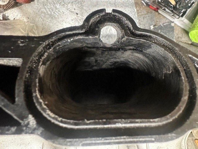
Then the last fun part – porting the intake manifolds. As I demonstrated in my previous post, there are several imperfections in the OEM manifold on a 3.8. I have to caveat that I didn’t use my DIY flow bench setup to measure the improvements or play with different port shapes, as there simply wasn’t time to develop them in the timeframe I wanted the engine to be complete by. However, what I did do was use some eBay listings to reverse engineer the good aspects of the 991 GT3 and GT3RS manifolds. They did demonstrate that those imperfections seen on my 997 manifolds were a result of mass production, rather than intention. So after a lot of research on the correct filler epoxy to use (seriously – thermoplastics are very interesting), I fixed the imperfections. This is done very simply by grinding the problem areas to “key” them, apply the epoxy, then finish the ports with sanding drums on a die grinder to get the shape nice and smooth.
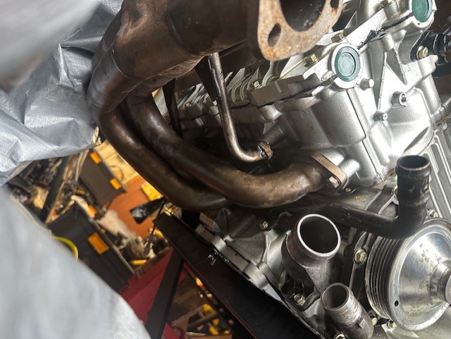
Finally, fitting it all into the car, and doing all the “while you’re there’s”. I’ll save the details of the process, but the “while you’re in there” list gets quite big. Here’s what’s new:
- Rear water cooling tubes, pipes, and heater hoses
- Rear brake hard lines
- Clutch and Dual Mass Flywheel
- Clutch Slave Cylinder and Hose
- Engine Ground Strap
- MAF, crank, cam sensors
- Variocam solenoids (yes, all four)
- Cleaned Injectors (Thanks to Tyler Harrop for using his injector cleaning machine)
- Oil scavenge pumps
- Engine Mounts
- Gearbox Mount (Thanks to Alan Smith for helping make a tool to install the new one)
- Air Oil Separator
- Spark Plugs
- Sports Cats
- Most fixings for things exhaust-related
- Differential seals
- Gearbox/Diff oil (Now on Millers CRX 75w90 NT+ competition gearbox oil)
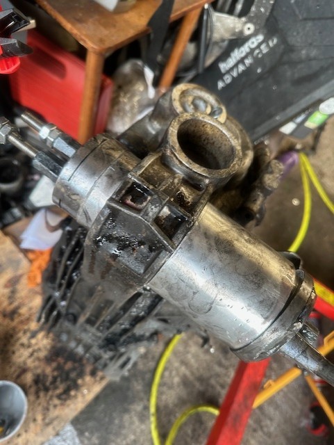
Gearbox bushing tool – note the two pulling rods.
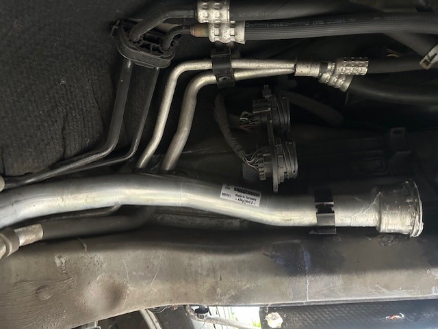
Factory fresh water cooling line.
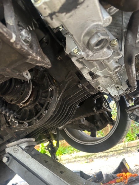
I chose to install the engine into the car with the gearbox separately fitted from underneath, as that was easier to manoeuvre on a driveway that’s not level. It takes a lot of time, swearing, and patience, but it is not impossible. I am also a convert to vacuum-filling coolant systems. Clearly, the Porsche 911 requires it because its layout makes air pockets very likely, which will cook a brand new engine. However, I have never found such a quick way to test for leaks, fill, and bleed a cooling system before.
Running the car in involved a good mix of load and deceleration on the engine to give the rings a fairly good workout. There are various research papers on the internet as to why you shouldn’t “baby” an engine for 1,000 miles, given the materials now in play, and why you follow a robust procedure with the right oil, which I won’t debate here. A 30-mile trip around Longridge on Millers competition running oil, followed by a change of oil and filter, to the same oil, did the majority of the work. I followed that up with a 250 miles combined, before swapping to the good stuff – Millers 10w60 NT+ CFS. So far, after 1,000 miles, I haven’t had any sign of oil consumption, even after thrashing it, and my oil pressure is great.
So, what’s left before I send the car to Wayne? Another (small) list
- A harmonically-damped underdrive pulley to be fitted, so play time at 8,000 RPM doesn’t prematurely knacker my ancillaries
- Another oil and filter change – Millers 10w60 NT+ CFS for 6,000 miles
- Acquire a GT3 throttle body and “smooth” plenum (Not an IPD with the wedge in) for a back-to-back dyno experiment
- Fit an FVD Oil Pan to increase the oil capacity and reduce the risk of starvation on track
- Potentially fit a modified oil pump – I have an idea of modifying the impellers with a really simple “old school” trick that should improve pressure across the board for track work. A post for another day
I’m aiming for Wayne to fix the flat spots in the map where I am clearly flowing more air than it used to, obviously raise the RPM limit now that the engine is built for higher RPM, and tweak the timing to suit the quench to see if we can get any more torque out of the beast. I did explore the possibility of mapping it myself on the dyno, having done courses and tuned several standalone setups before. However, I very quickly realised the tooling cost for the Bosch ECUs alone far exceeds the cost of asking the gent that’s done bespoke maps for 911s since the air-cooled days to have a fiddle.
For now, I am really happy to have the car back on the road and for it to be giving me a great analogue 911 experience. The motor definitely packs more punch than it previously did, to the point that it really does demand your concentration. The combination of my handling and braking upgrades really does make it a slightly sharper tourer, without compromising comfort. In my view, it’s what a Carrera S should be. It’s the ultimate compromise in a daily-driving sports car, just even better now.
I’d also like to say a big thanks to Porsche Centre South Lakes, especially Andrew Wise, who has been incredibly helpful, patient, and accommodating. The highlight being when a Porsche parts van arrived at my front door, with a fair few boxes getting carried into the hallway!
Leave a Reply